|
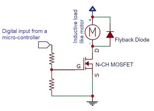
Hooman Fatoorehchi Assistant Professor School of Chemical Engineering University of Tehran, Tehran, Iran Formulas in this page are typed in $\LaTeX$. Applied Electronics N-Channel MOSFETs Remember to always "pull down" the Gate pin of the N-MOSFET. In this way you are sure your MOSFET stays off when there is no input signal. Otherwise, your MOSFET will maloperate. The pull-down resistor can be high (for instance, 10 kOhms); Like the one denoted by R1 in picutre below. If you are commanding the gate from a micro-controller or an ARDUINO module for example, remember to include a small resistor (R2=220 Ohms in the picture below) to ensure your micro-controller will not get damaged during switching on the MOSFET because of the high capcitative nature of the G-S connection. 
Similarly, you can use resistors-based voltage division to take care of the two mentioned points. See the following picture. 
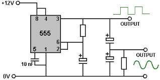
Sizing of Proper Heatsinks First we calculate the generated power in the intended piece using power equations like $P = V \times I$ or $P = \frac{V^2}{R}$. Second, we read the maximum junction temperature of the piece from its datasheet. Let's denote it by TJ. We also read the junction to case thermal resistance, denoted by $R_{thJC}$, in $\frac{^oC}{W}$. So, the maximum case temperature can be $T_C= T_J-R_{thJC}\times P$. Now, we assume the maximum ambient temperature (summer case) as $T_{amb}$. Finally, we have to choose a heatsink whose thermal resistance plus that of the conductive (insulator) pad be LESS than $R_{th}=\frac{T_C-T_{amb}}{P}$, in $\frac{^oC}{W}$. 555 IC Sine Wave Generator (Inverter) 
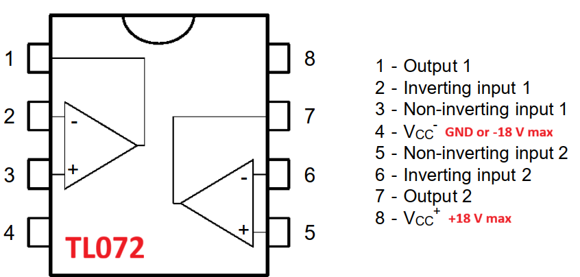
TL072 OpAmp IC I have made Chua's chaotic circuit using this OpAmp. 
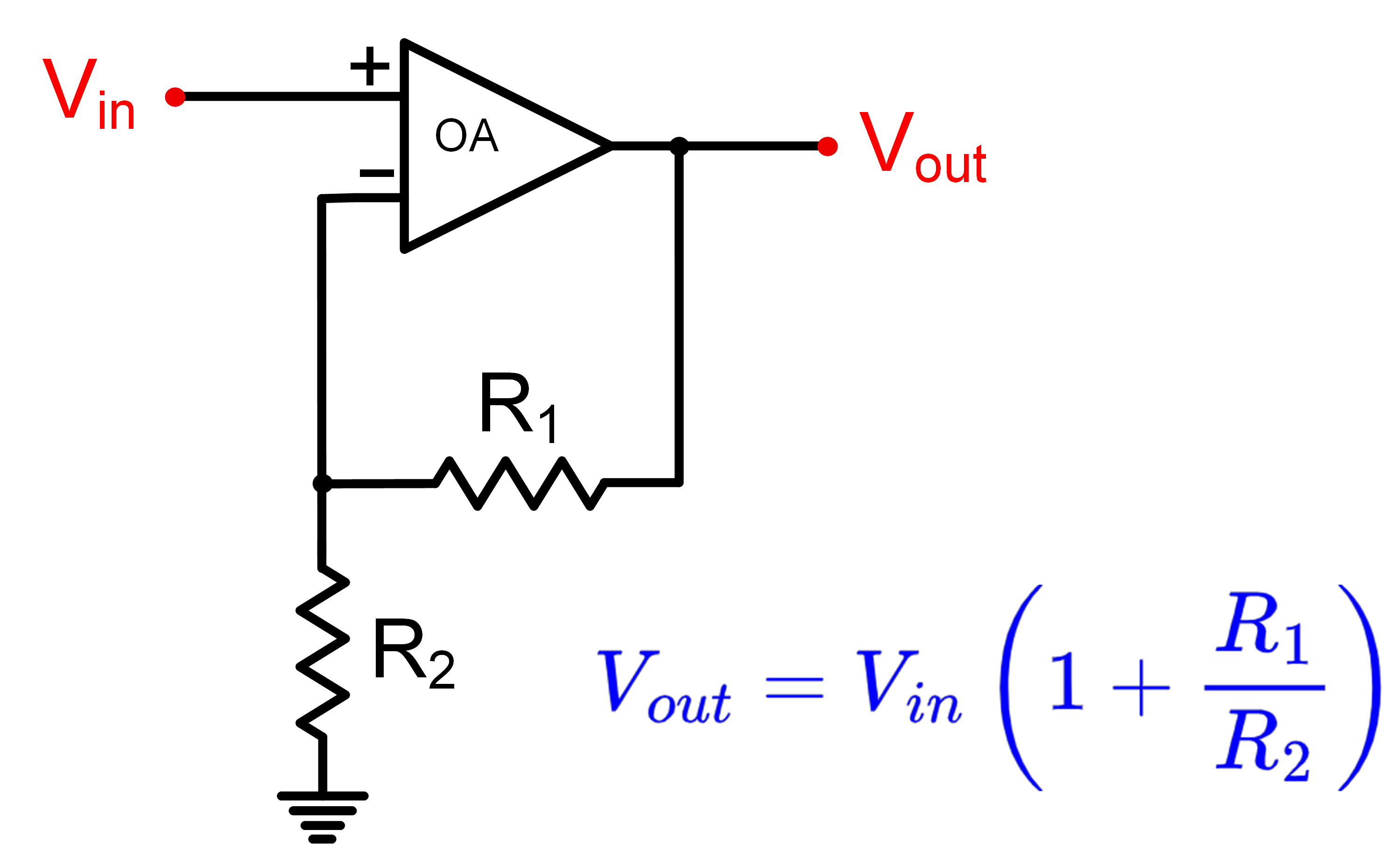
Non-inverting Operational Amplifier Configuration 
|
